Welcome to my personal website. My name is Gavin Lim and I am a Senior Electrical Engineering student (Class of 2019) at the University of British Columbia (UBC) in Vancouver, Canada. On this site, you will find the credentials that I have accomplished from my education, internships, and personal projects over the last four years. Any overview of my skillsets are listed below:
Software
C, C++
MATLAB
Python
Html, CSS
Electrical
Cadence Allegro
Altium Designer
LTSpice
SMT soldering
Mechanical
SolidWorks (3D Printing)
Power Tools
Education
University of British Columbia
Bachelor of Applied Science, Electrical Engineering, Sept 2015 - May 2019
Relevant Course Topics:
System Software Engineering (CPEN 333) - 94%
Signal and Image Processing (ELEC 421) - 78%
Power Electronics (ELEC 451) - 80%
Bachelor of Science, Honours in Biotechnology, Sept 2010 - May 2015
Coursera
Python Data Structures - University of Michigan, Dr. Charles Severance
Lorem ipsum dolor sit amet, consectetur adipisicing elit. Mollitia neque assumenda ipsam nihil, molestias magnam, recusandae quos quis inventore quisquam velit asperiores, vitae? Reprehenderit soluta, eos quod consequuntur itaque. Nam.
The UBC Sailbot is a student-run engineering team with a purpose of designing and building unmanned and autonomous robotic sailboats. The team's latest endeavour is the Trans-Atlantic challenge in 2016, where our 5-meter long robotic sailboat, Ada, embarked on a journey across the Atlantic ocean from Newfoundland, Canada to Ireland.
Presently, the team's next challenge is to complete the 2020 Vic-Maui Yatch Race by building a new 5-meter long sailboat named Raye.
Involvement Time: 3 Years
Things I learned:
How to integrate off-the-shelf components to obtain free energy from the sun without creating magic smoke
What to consider when choosing components for creating a solar-powered system (ie: Solar PVs, Batteries, BMS, MPPT, wire gauge)
How to ensure a 10+ person electrical team is functioning like a well oiled machine* (results may vary depending on proximity to exam season)
How to obtain and explain the charge and discharge characteristics of 18650-based Li-Ion batteries
What to consider when placing communication sensors on a boat (ie: GPS, LTE, Wifi, Satellite, AIS)
Ada being loaded into the waters
Introduction
As lead in the Electrical team, my job is to ensure the relevant electrical projects for our next boat, Raye, are progressing in a timely and efficient manner. On top of ensuring that each members are fully engaged with their projects, my duties also include liasing with internal subteams (ie: Mechanical and Software) and external groups (ie: Sponsors and Vendors). My mantle of responsibilities cover the following projects:
Antennaes (LTE, WiFi, GPS, Satellite)
Power System (Solar PV, Batteries, BMS, MPPT)
STM32-based Low Voltage Detection Module
Motor Protection Circuit
Electrical Team Photo, 2017
Discussion
Prior to a managerial role, my previous engagements within the Sailbot focused on the extensive development and testing of the team's current power system, which encompasses the solar panels, battery management system, maximum power point tracking module, and Li-Ion batteries. In brief, the purpose of each components are as follows:
Solar Panels - Convert photons from the sun into electricity
Battery Management System (BMS) - Ensures the charging and discharging process of each individual 3.6V Li-Ion batteries is controlled and maintained in a safe manner
Maximum Power Point Tracking (MPPT) module - Maximizes the output power obtained from the solar panels
Li-Ion batteries - Energy storage. Contains 18650 batteries.
Diagram of power system shocasing the connections between components.
In the final phase, Raye will contain four solar panels and ten 18V batteries (final number subject to change depending on power needs vs weight constraint). Each battery requires its own BMS module to ensure consistent and efficient charging and discharging, while each solar PV requires its own MPPT to maximize power generated. For testing purposes, the diagram above shows how the power system will be generally implemented.
Testing the effects of sail shadow orientation on solar panel power output.
Battery Management System (BMS) from Energus.
18650 Battery modules
Similar to Ada, Raye's solar panels will be placed on its deck. As a result, considerations must be made in regards to the presence of the boat's mast, which in turn will cast a shadow onto the panels. Depending on the time of day, the effect of the shadow can be drastic to the point of reducing the power output by 90%. The figures above showcase testing excursions of the solar panels.
To observe a typical charging characteristic of the power system, the input battery current and battery voltages are measured and logged over time in view of the sun with partial cloudiness.
Power System. Shown: MPPT, Batteries, and BMS.
To improve mobility, a custom cart is built to house all the power system components.
The figure above provides a reference on the impact of sky conditions on solar panel power output. The key take away from this figure is that cloud cover will cause inconsistent and unreliable power output!
Charging characteritic of 18V batteries. Drastic drops in charging current during the initial 40 mins of charging are caused by the effects of cloudy conditions.
During the initial charging phase, overcast and periodic cloud covers affect the power output generated by the solar panels. This is represented by sharp drops and inconsistent average current output during the first 40 mins. Between the 15 min and 19 min time mark, the amount of irradiation reaching the panels has decreased below a threshold such that zero power output is produced. This event was attributed to the temporary blockage of the sun by clouds. Beyond the 40 min point, the fair weather condition generates a steady current of 5A which led to an increase in battery voltage to 17.6V (nominal: 18V).
Conclusion
The charging plot of the battery system provides an outlook of the impact cloud covers can have on the boat's power system, where brief overcast can have a dramatic impact on the system's ability to generate consistent power. As a result, weather conditions must be considered in the boat's navigation trajectory as a means of ensuring consistent and reliable power generation. With the tested power configuration, the maximum output current generated was 5.3A and the charging time from 16.4V to 17.6V of nominal 18V Li-Ion batteries required approximately 1 hr 40mins.
As part of my senior capstone project in a team of four, I am building a robotic rover with localization and navigation capabilities. Onboard sensors for localization are a Phidgets 3/3/3 High Precision IMU, and a Phidgets GPS, while an Intel NUC housing an i3 processor and an arduino nano will be used for navigation.
Involvement Time: 8 months
Note: To ensure adherence to the NDA and IP agreements with FPInnovations, certain specific details will be omitted from this project portfolio.
Things I am learning:
How to implement IMU, GPS, and ultrasonic sonic sensors using ROS
How to implement Kalman filter to acquire the best estimated position of the rover
How to implement a feedback control system based on reference postioning in controlling a rover's navigation
How to design the power system of a mobile robot
Introduction
The client of the project, FPInnovation, is a non-profit research group aimed at fostering technological innovations in the forest industry.
Within this industry, the quality of a log is proportional to its final economic value. Distribution of hardwood, softwood, and knots are some of features that affect the log's overall quality, which can be determined using CT scanning. Current logistical procedures for determining a tree's quality involves logging and transporting the log to a scanning facility.
The purpose of the rover is to provide a more economical and faster alternative in acheiving log quality measurements. By having a mobile CT scanning rover, logs will not longer need to be transported back to the facility, thereby saving time and resources.
Note: All information depicted in this portfolio were completed by me.
Objective
The functional concept of the rover is to perform CT scanning of a log by traversing alongside it in a parallel direction. While the final rendition of the rover within the scope of this capstone project will not house an x-ray producing device (for safety reasons), the positional and navigational expectations will be implemented. To achieve these expectations, the rover will house the following components for positional and navigational capabilities:
Inertial Measurement Unit (IMU)
GPS
Ultrasonic Sensor
Processor
Microcontroller
Discussion
The figure below illustrates the ROS computation architecture which shows how the robot's firmware will function. For a quick refresher on ROS concepts, refer here. There are three parts of this architecture:
Navigation and Communication System
Motor Control System
Localization System
ROS computation architecture. Sensors are located in the Localization System, which send their respective data to the Kalman Filter for positional estimation.
Focusing on the IMU's role in the Localization System, the rover's acceleration, angular velocity, and linear velocity can be obtained using the device. PhidgetSpatial Precision 3/3/3 High Precision was selected because of its readily available API and company firmware support. The IMU sensor is connected to a ROS node named "IMU_node", which advertises the relevant imu data to a topic named "/imu_data".
PhidgetSpatial Precision 3/3/3 High Precision
Because the Phidget C++ API is not implemented in ROS, a driver is required. The phidgets_imu package (phidgets_imu_node) contains the required drivers to display the raw linear acceleration and angular velocity in the topic, /imu/data_raw. To fuse the angular and linear accelerations into orientation information, the imu_filter_madgwick package (/imu_filter_node) is used, which in turn publishes the fuse data on the imu/data topic.
ROS contains a native simulation tool made for teaching ROS and ROS packages that is represented by a turtle in the x-y plane. The node, /imu_node, is used to relay the positional information containing linear and angular velocity from imu/data to the turtle simulation.
IMU firmware architecture.
Demonstration of the imu's firmware architecture is presented below, where performing yaw rotations of the imu will cause the turtle in the simulation to turn accordingly:
Conclusion
This project is still ongoing and therefore inconclusive.
This is a relatively simple project that I undertook as a means of spending time with my girlfriend while sharing my love for electronics. What started as a bonding event ended up being an annual tradition that involves the following procedures leading up to the 25th of December:
Step 1: Brainstorm and design a rough sketch of intended sweater motif
Step 2: Spend the day together at a mall looking for a cozy sweater
Step 3: Buy art supplies (ex: felt sheets) and electronic supplies (ex: LEDs, wires)
Step 4: Delegate project tasks into two roles: (1) Art Designer and (2) Electronic Designer
Step 5: Initiate construction! (Note: construction of the sweater may take up to 12hrs due to non-essential distractions like eating, snacking, and TV-watching)
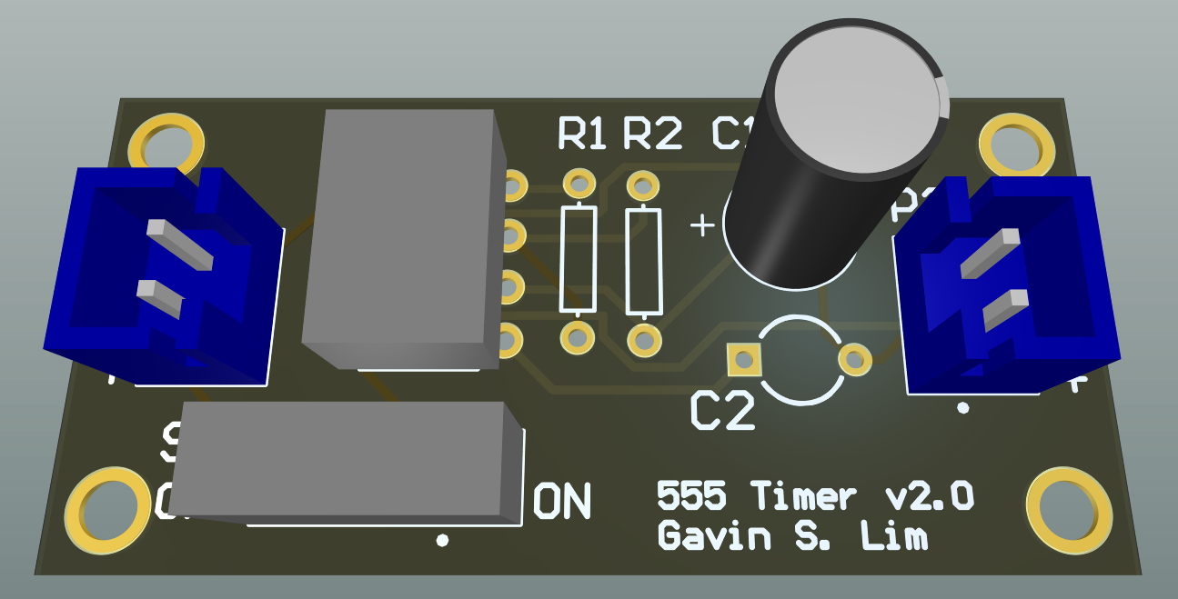
The resulting sweaters have LEDs mounted on them that flash at a constant frequency and duration. Below is a slideshow of the three sweaters made in 2015, 2016, and 2017 respectively. The slide shows the progression and increasing "finesse" of the sweater's electronics, where in both 2015 and 2016, a single-sided prototype board was used to house the circuit. In 2017, I opted to create my own custom PCB using Altium Designer in order improve the circuit's durability, appearance, and size. For a video demonstration of blinking effects, refer to the end of this portfolio page.
Note: Unfortunately, the 2018 sweater edition was not created due to other engagements during the holidays.
Sweater 2015
Christmas Tree Edition
Sweater 2016
Santa Edition
Note: Picture illustrates the sweater in the midst of construction
The blinking effect is achieved using a LM555 timer operating in astable mode, which allows the IC to generate a square wave output. In brief, the frequency of this wave is determined by two resistors (R1, R2) and a capactor (C1). Based on LM555 datasheet, the equations below dictate the duty cycle of the squave wave:
$$t_{on} = 0.693 \cdot C_1 \cdot (R_1 + R_2)$$
$$t_{off} = 0.693 \cdot C_1 \cdot R_2$$
$$T = t_{on} + t_{off} = 0.693 \cdot (R_1 + 2R_2) \cdot C_1$$
The respective values of the passive components were chosen below based on component availability:
$$C_1 = 220uF$$
$$R_1 = 1kΩ$$
$$R_2 = 4.7kΩ$$
This results in the following characteristics of the square wave function:
$$t_{on} = 0.869ms$$
$$t_{off} = 0.713ms$$
$$D_{on} = 0.55$$
The figures below show the progression of the PCB from layout placement to component population. Top left: board layout; top right: 3D model; bottom left: manufactured PCB; bottom right: populated board.